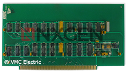
Description
About the Fadal 1040 Boards
Specifications:
Part NumberPart Number
- PCB-0005 1040-2A/2B MILL CARD
- PCB-1040-1 MILL CARD
- Remanufactured
- One Year Warranty
Located in 1060 Motherboard Slot 17.
The Mill Interface Board (1040) interfaces the control to the relays, switches, sensors and keyboard. It takes the CPU commands and activates the relays to perform the commanded task. Reads the sensors, switches and keyboard and sends the information to the CPU via Computer Interface Board.
Compatibility:
All 1040 dash numbers are compatible with all versions of the 1400 CPU boards; 1400-1 to 1400-5. Except, the 1400-2 board was designed specifically for the Fadal Pallet Changer.
Testing the 1040 board.
First. the 1040 boards have backwards and forwards compatibility so the simplest test is to swap with another board if you have more than one Fadal Machine. Except machines with the Pallet Changer requires the 1040-2 hardware version.
The second option would be to use the internal controls Menu diagnostics.
To begin, at the prompt “ENTER NEXT COMMAND” enter the following commands:
Display Switches Status:
To enter the Switch Diagnostic System, enter the DI command. The Diagnostic System recognizes the following commands:

This command causes the continuous display of switch feedback and CNC status data. The display is updated 3 times per second. The display will be continuous until the “X” command is entered. Once in the “DS” mode, the maintenance engineer may return the CNC to the normal command mode by depressing “ENTER” without first typing a command (or by simply depressing “ENTER” twice in succession). The data display will continue during the execution of normal machine functions, however, it is not recommended that he CNC be left in the “DS” mode during the actual machining of production parts.
The “DS” mode is terminated by entering the Diagnostic System via the “DI” command and then issuing the “X” command. The switch status values are displayed as zero if the switch is open and as one if the switch is closed.
Counts are displayed as two digit hexadecimal numbers.
A description of the display follows:

Menu Diagnostics:
From ENTER NEXT COMMAND enter the following commands
DI <PRESS ENTER>
G 0 3000 <PRESS ENTER>
After entering the above commands, the first of 5 menus will appear. The space bar switches between each menu and the MANUAL key is used to abort a test (Hold this key down until the computer aborts a test).
Locate MENU PAGE 4
Function 4 = TEST MILL INTERFACE CARD (1040)
This test takes a snapshot of all the inputs and continues checking for any state change in the input status or if the MANUAL key is press to abort the testing procedure. During the loop test, the test is stopped and a message is displayed if any one of the input changes. For example, if the spindle is rotated passed the orientation magnet and the input state changes a message will be displayed. This test could be left to run all day or over night to verify the board is functioning. This test can also be used for finding loose connection where "wiggling" connections/wires while this test in looping. A break in the connection will display a message.
To exit the Menu Diagnostics, locate the START CNC menu, select it and type G and the letter O to return back to the CNC operation.


