

Resolver Failures
Published by David de Caussin on Dec 16th 2018
Resolver Faults:
A resolver fault occurs when the axis controller card doesn't detect the returning sine wave signal from the resolver. The originally the resolver signal originated from the clock board and was shared by all the axis motors. If one resolver shorts the sign wave; all or randomly the resolvers would fail.
We modified the 1060 motherboard to accept the the 1060-0-1 board (PCB-0010). This small "daughter" board creates a separate the signal for each individual motor and help identify which axis is actually failing. Some call it a Tester Board when actually it is a signal isolation that takes one signal and creates 5 independent ones.
This board could be bad and not allow the resolver excitation signal to reach the resolver. Early model machines did not have this daughter board.
It is important to verify the bottom "bullet" connector that plugs into the 1010 axis card doesn't have a loose connection inside the bullet connector.
Another potential failure is with the resolver connector at the motor. The six pin Molex has been know to fail and give a marginal connection. You can put pressure on it in various direction while having someone try and reset the fault. Do a visual examine inside the Molex connector and look for corrosion. Replace the pins if necessary, we seen the pins inside the connector virtually gone.
The resolver bearings can fail and cause problems with the signal. Bearing failure is often due to the misalignment of the motor end shaft and the resolver shaft. The typlical Helical coupler does not allow for parallel shaft misalignment over .005" and simply replacing the resolver will eventually fail again. You need to replace the resolver coupler with a better designed coupler. Contact us for more information.
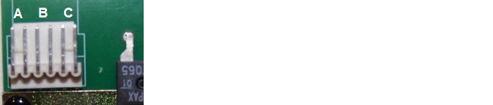
Testing a Resolver: You can test a resolver to see if it is indeed bad by using a voltmeter and measuring the resistance of the coils inside the resolver. The Resolver is constructed of three coils; two excitation coils and one reference coil that is connected to the axis controller card.
The image shows the interface connector and the associated coil connections.
1) Check Resistance:
Pair A = 70 to 80 Ohms
Pair B = 190 to 220 Ohms
Pair C = 190 to 220 Ohms
B and C will have the same values; the actual value depends on the manufacture.
2) Check for Coil-To-Coil shorts:
Any other pin combination besides the three individual pairs must result as an open circuit.
3) Check for Short to ground:
Check resistance of each pin to Resolver frame (case). They must not be shorted to the resolver frame.
4) Check the voltage when connected:
Pair A = 1.7 VDC
Pair B and C = 3.5 VDC
Pair A goes directly to the 1010 axis card; J2 bottom bullet connector
TOTAL ENGINEERING SUPPORT - with us you're not just getting the usual "Part In A Box!"
Here's four key examples of the Total Support our customers receive:
Diagnoses - Direct help in determining if you really do need to replace the part. When working with engineers that design the machine, we can help determine if there's other elements in the system that also need to be addressed before replacing a suspected failed part.
Documentation - We provide very simple and concise, step by step enhanced instructions on how to install and get your replacement part in and running. With our documentation we also include Preventative Maintenance tips to help avoid future failures.Warranty - Just like "the old days", we value our relationship with each and every customer. We are driven by fairness and committed to your satisfaction. Click on the About Us page to learn about what made Fadal so successful and how it guides us today.
Support - With the combination of our Fadal engineering knowledge and direct interaction with Baldor and Glentek engineers, you are getting the absolute best product support possible at installation and beyond.
STOP BUYING PARTS YOU DON'T NEED!