

Fadal DC Brush Amplifier Adjustment
Published by NXGEN CNC on Feb 21st 2020
Click here for a PDF printout of this manual.
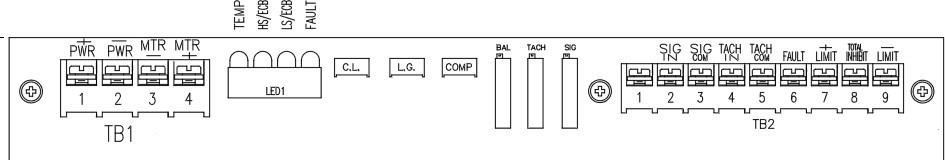
All amplifiers need adjustment after installation. The adjustment is basically the same for all DC brush amplifiers. Above are the Glentek amplifiers, these instructions are the same for the AMC amplifiers.
AMP-0021
AMP-0006
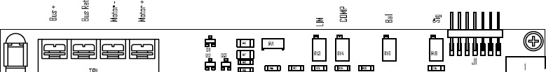
Some potentiometers adjustments are dependent upon your amplifier model and version. Skip adjustment if you don’t see the Pot on your amplifier because it has a fixed value.
Potentiometer Definition:
1) Signal Gain Pot
The SIG Pot affects how the amplifier converts the input signal to an RPM value. A low adjustment will cause the machine not to get up to the Rapid Traverse speed and it will generate a MOTOR OVERLOAD fault; a high adjustment will cause the machine to sound “crisp” and “bang” or as it moves.
2) Balance Pot
The Balance Pot adjusts the offset of the Signal pot so as to be the same in both directions.
3) Loop Gain
The LOOP or L.G. pot is adjusted fully clockwise for maximum servo stiffness.
4)Current Limit
The Current Limit (C.L.) or LIM pot adjusts the amount of current that can go out to the motor. Fully clockwise provide maximum current
5) Compensation
The COMP pot adjusts the overall response time of the servo system.
Note: At Power-On, the Axis Controller card will try to rotate the motor as a power-up test. Failure to rotate causes an ERROR #1 or #3. When installing a new amplifier, this Error E-stop can be caused because the amplifier cannot rotate the motor until adjusted correctly. Check initial adjustments before powering on. If this continues, rotate the SIGNAL Pot. more CW and try again.
This test can be temporally eliminated until adjustments made by installing a jumper at J8 of the 1010 axis controller card. When using the J8 Jumper, it’s a good practice to power up the machine with the E-stop button down then release it manually, watching for any possible run away condition when the system powers up.
DC Amplifier Adjustment Procedure
Machine with Scales:
Before adjusting the amplifier, verify that scale cable (if applicable) is disconnected from the 1010 axis card of the corresponding axis amplifier to be adjusted. If it is connected (using the glass scale feedback), power down the machine, disconnect the cable, and then power up the machine. See parameter note for Rotary Scale at the page of these instructions.
The scale feedback is the upper blue, edge connector; the bottom connector is for the motor encoder feedback (do not remove).
After the amplifier is adjusted you’ll need to power down the machine and install the scale connector.
Adjusting the amplifier:
1) Turn the Loop Gain potentiometer all the wayclockwise.
2) Turn the Current Limit potentiometer all the way clockwise. Full current is set by turning the pot fully clockwise. For the large DC motors (6000 series) the pot is set fully clockwise. For smaller motors (4000 series) the value can be reduced after final adjustments. Not enough current will cause the machineto fault during a rapid move and display the message “MOTOROVERLOAD”.
3) Slowly turn the Compensation potentiometer counter clockwise until the axis motor produces a High frequency vibration (Buzz), then turn the potentiometer clockwise until it stops buzzing and add one more full turn clockwise from thatpoint.
4) Begin cycling the machine to adjust the Signal Gain and Balance potentiometers. Enter the following program if adjusting an X, Y or Zaxis:
N1 M91 M49 G91 F150. N2 G1 X-3.Y-3.Z-3.
N3 X3.Y3.Z3.
N4 M99 P2
Enter the following program if adjusting a Rotary axis amplifier:
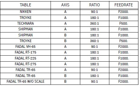
First select the Feedrate using the ratio table on the last page and use it in line 2 of the program below for the F*** value.
N1 M91 M49 G91 N2 A-90. G1 F*** N3 A90.
N4 M99 P2
5) Press AUTO, to start the programrunning.
6) Turn the Signal Gain potentiometer until the CNC display of the axis to be adjusted reads the correct following error count while running the program.
Clockwise will reduce the following error and counterclockwise will increase the value. The following error is the number displayed to the right of the position display value.
- For Metric Ballscrews the target value is 302.
- For Inch Ballscrews and Rotary tables the target value is 595.
Use the SETP command to check the current Ballscrew Type if you’re not sure about which ballscrew you may have.
The goal of the adjustment is to match the other axes so the system is dynamically balanced with all the XYZ axes. It’s not required to be exactly set the value, it can be; +- 10 counts, in most cases. However it does somewhat affect the contouring accuracy; the closer the better.
7) Press the SLIDE HOLD key and adjust the Balance potentiometer of the amplifier to read a following error between +1 and -1.
8) Press the START key and the program will start again. Verify that the following error is still correct starting from step 5above.
9) Press the SLIDE HOLD key to stop the machine. Press the MANUAL key and then type SETCS and HO, to send the machine home. Adjustment of the amplifier is complete.
Rotary Feedrate Selection Table
Note for Rotary Scales:
When disconnecting the rotary scale to adjust the amplifier, you must verify the SETP axis ratio has the correct mechanical ratio. For example the TR65 B axis normally has the SETP set to a 180 to 1 ratio (when using the scale). It must be temporally set to90:1 to adjust the amplifier without the scale feedback. Using the SETP command, set the B axis ration back to 180 to 1 after adjusting the amplifier. Changing the ratio requires cycling the power to the machine(off/on).