

Brushless Amplifier Adjustment
Published by NXGEN CNC on Dec 23rd 2019
Click here for a PDF printout of this manual.
All brushless amplifiers need adjustment after installation. There are three pots that will need to be adjusted:
1) Compensation Pot
The Comp. affects how fast or stiff the servo becomes. The system is designed to be adjusted on the edge of instability. You’ll turn the Pot until the axis buzzes then back off until it stops.
2) Signal Gain Pot
The Signal Pot affects how the amplifier coverts the input signal to an RPM value. To low and the machine won’t get up to the Rapid Traverse speed and generate a MOTOR OVERLOAD fault; to high and the machine will sound to crisp and “bang” as it moves.
3) Balance Pot
The Balance Pot adjusts the performance of the Signal pot so as to be the same in both directions.

Note: At Power-On, the Axis Controller card will try to rotate the motor as a power-up test. Failure to rotate causes an ERROR #1 or #3. When installing a new amplifier, this Error E-stop can be caused because the amplifier cannot rotate the motor until adjusted correctly. Check initial adjustments before powering on. If this continues, rotate the SIGNAL Pot. more CW and try again.
This test can be temporally eliminated until adjustments made by installing a jumper at J8 of the 1010 axis controller card. When using the J8 Jumper, it’s a good practice to power up the machine with the E-stop button down then release it manually, watching for any possible run away condition when the system powers up.
AC Amplifier Adjustment Procedure
Machine with Scales:
Before adjusting the amplifier, verify that scale cable (if applicable) is disconnected from the 1010 axis card of the corresponding axis amplifier to be adjusted. If it is connected (using the glass scale feedback), power down the machine, disconnect the cable, and then power up the machine. See parameter note for Rotary Scale at the page of these instructions.
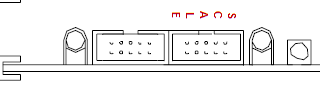
The scale feedback is the upper blue, edge connector; the bottom connector is for the motor encoder feedback (do not remove).
After the amplifier is adjusted you’ll need to power down the machine and install the scale connector.
Adjusting the amplifier:
1) Turn the Loop Gain potentiometer all the way clockwise (a clicking sound will be heard when the pot has reached the limit).
2) Slowly turn the Compensation potentiometer counter clockwise until the axis motor produces a High frequency vibration (Buzz), then turn the potentiometer clockwise 1-1/2 turns.
3) Begin cycling the machine to adjust the Signal Gain and Balance potentiometers.
Enter the following program if adjusting an X, Y or Z axis:
N1 M91 M49 G91 F150.
N2 G1 X-3.Y-3.Z-3.
N3 X3.Y3.Z3.
N4 M99 P2
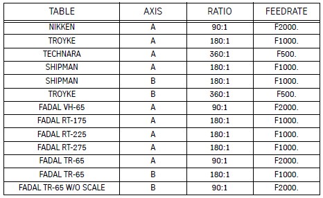
Enter the following program if adjusting a Rotary axis amplifier. First select the Feedrate using the ratio table on the last page and use it in line 2 of the program below for the F*** value.
N1 M91 M49 G91
N2 A-90. G1 F***
N3 A90.
N4 M99 P2
4) Press AUTO, to start the program running.
5) Turn the Signal Gain potentiometer until the CNC display of the axis to be adjusted reads the correct following error count while running the program.
Clockwise will reduce the following error and counterclockwise will increase the value.The following error is the number displayed to the right of the position display value.
For Metric Ballscrews the target value is 302.
For Inch Ballscrews and Rotary tables the target value is 595.
Use the SETP command to check the current Ballscrew Type if you’re not sure about which ballscrew you may have.
The goal of the adjustment is to match the other axes so the system is dynamically balanced with all the XYZ axes. It’s not required to be exactly set the value, it can be; +- 10 counts, in most cases. However it does somewhat affect the contouring accuracy; the closer the better.
NOTE: If your machine is displaying the axis load %, you’ll need to use the SETP command to change the display setting parameter for “Display the axis following error or Load?” and set it to FOLLOWING ERROR. This setting only affects the display; nothing else.
6) Press the SLIDE HOLD key and adjust the Balance potentiometer of the amplifier to read between 0 - 1.
7) Press the START key and the program will start again. Verify that the following error is still correct starting from step 4 above.
8) Press the SLIDE HOLD key to stop the machine. Press the MANUAL key and then type SETCS and HO, to send the machine home. Adjustment of the amplifier is complete.
Rotary Feedrate Selection Table
Note for Rotary Scales:
When disconnecting the rotary scale to adjust the amplifier, you must verify the SETP axis ratio has the correct mechanical ratio. For example the TR65 B axis normally has the SETP set to a 180 to 1 ratio (when using the scale). It must be temporally set to 90:1 to adjust the amplifier without the scale feedback. Using the SETP command, set the B axis ration back to 180 to 1 after adjusting the amplifier. Changing the ratio requires cycling the power to the machine (off/on).